Specs
Why redesign the PCB at all?

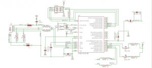
Some of you might ask yourselves why not just interface with the Bluetooth already built into the controller and connecting to another Bluetooth transceiver on an Arduino. As far as I could find out online, the only way to do this is to connect the controller to a computer, run it through a program and then send it over to the Arduino. Since that isn’t straight forward and you might not always have a PC around when trying to steer that robot you built but you really like the ps4 controller, and further more I actually don’t have the programming skills to interface through a Bluetooth protocol, so it might be a better solution as a whole to redesign the PCB so now you know what’s on it and how it works (of course Sony doesn’t release their schematics) and you can interface directly with it. Moreover now I can actually make it compatible with as many things as can be thought of since things like nRF, BLE, WIFI, ZIGBee, etc. can all be modular options without needing to make major configurations to the controller.
Why base the design of an Arduino ATmega2560?
Arduino is a very widely used microcontroller and it is used for the vast majority of prototyping applications out there when it comes to things like automation, robotics, etc. so it might be useful for a lot of other people apart from me who are going through the same frustration. Basing the design around this very specific board/chip has got to do with the amount of pins available on it which means I can designate a separate pin to each of the buttons, inputs, LEDs and still be able to run out even more breakout pins from the back without worrying about having enough pins. On top of that it is very easy to program Arduinos making this a project anyone can make.